MacRead Studio 1.0 pavement design suite
Design model for strength and position of geogrids for road base stabilization
Technical Note on MacRead Studio (MacRead 2.0, Geogrid Design, Giroud Han, LengGabr, BCR Sand, Static Method)
Geosynthetics are extensively used for the improvement of soils characterized by low mechanical performances in order to carry paved and unpaved roads and to provide the following stabilizing mechanisms:
- base course lateral restrain mechanism for horizontal stresses generated by the soil self-weight;
- base course lateral restrain mechanism for horizontal stresses generated by wheels loading;
- tensioned membrane mechanism at the base or subbase – subgrade interface.
Each of these three mechanisms produce tensile forces in the geosynthetic layers.
The tensile forces produced by the soil self-weight and by the tensioned membrane mechanism at the base or subbase – subgrade interface are static loads by nature, while the tensile forces produced by wheels loading are dynamic / cyclic in nature; however in each instant the load produced by wheels is added to the other two static loads.
The design methods presently available provide contains no/or insufficient indications about the number of required geogrids layers and the mechanical characteristics thereof. Hence a new design method has been developed which accounts the design of geogrids for road base stabilization, based on a 4 layers model: asphalt (binder and wearing course), in case of paved roads; base, subbase, subgrade. Once the base and/or subbase thickness has been defined with one of the available methods in literature (AASHTO method, Giroud – Han method, Leng – Gabr method, etc.) it is already appropriate for providing the structural capacity of the road to resist the design number of wheel passages for the whole design life of the road.
Given this thickness, by considering separately the effect of the static loads (soil self-weight and tensioned membrane mechanism) and the instant effect of wheel load, it is then possible to calculate the distribution of the horizontal tensile forces in the whole road structure and the overall tensile forces generated in each layer of geosynthetic, and then to select the appropriate geosynthetic for each layer based on a limit state criterion.
The proposed design method allows to set the number and the mechanical characteristics of geosynthetics layers required for absorbing the horizontal forces generated by self-weight, wheel load and membrane effect. Obviously, more important is the road structure we are designing and lower the design geosynthetic strain shall be: hence for important structures the geosynthetic strain may be limited to 2%, while for less important structures (or when the design conditions afford slightly larger deformations) 3%, 4% or5% geosynthetic strain may be acceptable.
Case histories in South Africa and Uganda will be reported where this method was used successfully.
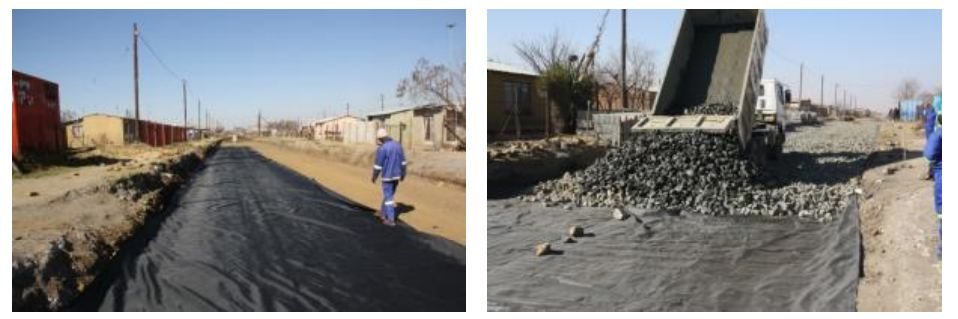
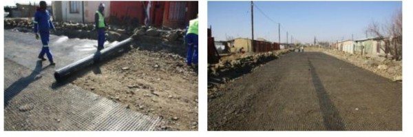
2.1 CASE HISTORY 1: Unpaved Road Secunda – Mpumalanga (Republic of South Africa)
DESIGN BY LengGabr + Geogrid Design
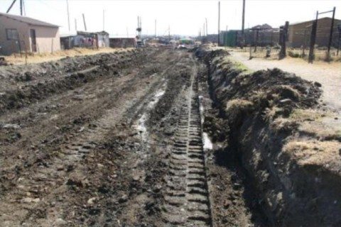
A Reconstruction and Development Programme taking place near Secunda in Mpumalanga (Republic of South Africa) required the improvement of the road infrastructure, from gravel to paving block surface road. In a particular stretch about 600m long, soft soil was encountered at 0.5m deep from natural ground level. The original design reported in Figure 3 required a rock pioneer layer of 350mm which would have caused major construction issue and most important, it would have impacted on the budget which most surely would have brought the project to a standing still.
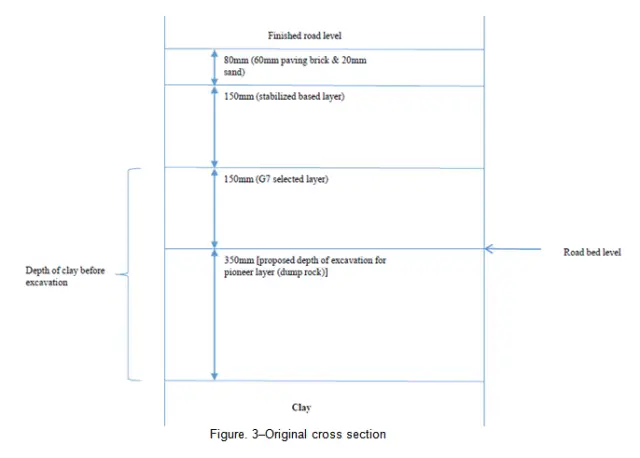
Figure. 3 – Original cross section

The Leng-Gabr method was used to calculate the reduction in pavement thickness of the rock layer. Back analysing the model in order to match the layer thickness, an overall CBR for the whole pavement was considered as follow:
Input data:
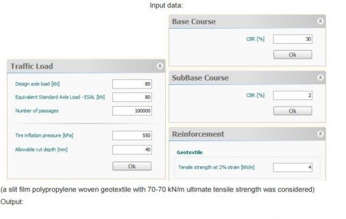
(a slit film polypropylene woven geotextile with 70-70 kN/m ultimate tensile strength was considered)
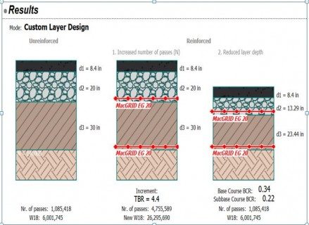
Output :
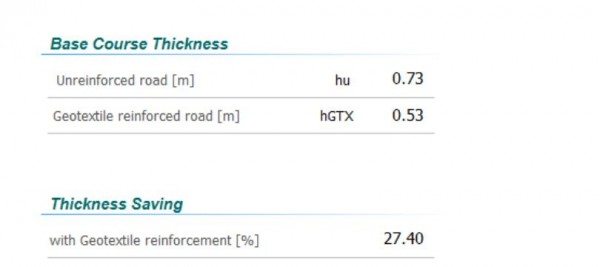
The pavement thickness using the geotextile reinforcement reduces from 730mm to 530mm.
The Leng-Gabr method yielded the following result: the rock layer thickness with the woven geotextile reinforcement can be reduced from 350 mm to 150mm.
Therefore the total thickness of the pavement has reduced from 730 mm to 530 mm.
Since the reduced total thickness is still very large for a single geotextile reinforcement, the above outlined Geogrid Design method was used to check the effective reinforcement requirement: the selected in put data are reported below Table 2:
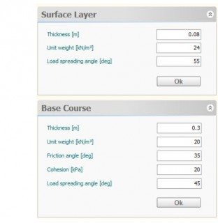
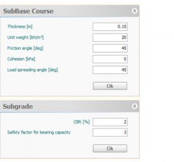
Table 2 – Input data selected for Example 1
The geogrid design model resulted in the following section as shown in Table 3.
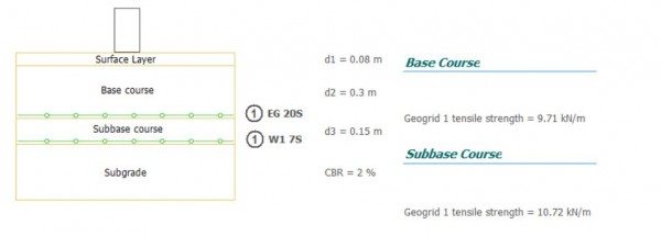
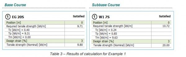
Table 3 – Results of calculation for Example 1
The woven geotextile at the subbase – subgrade interface has to work at 3 % strain, rather than 2 %considered in the Leng-Gabr method, producing 9.63kN/m tensile strength for the tensioned membrane effect Tm, which is not considered in the Leng-Gabr method; moreover an extruded biaxial Polypropylene geogrid, with 20-20 kN/m ultimate tensile strength is required to reinforce the 300 mm thick base layer:
MacGrid EG 20S (Extruded Geogrid 20 kN/m);
MacTex W1 7S (Woven Geotextile 70 kN/m)
thisgeogrid will work at 3 % strain as well. Considering that the pavement is made up of articulatedconcrete blocks, that is a very flexible pavement, such strain level is considered to be appropriate.Note that for the geogrid in the base course the prevailing tensile forces is the Tp force due to the dynamic load produced by wheels, while the tensile force Tz produced by soil self-weight corresponds to 5% of the ultimate tensile strength of the geogrid; at this tensile level the long term creep deformation of the geogrid can be assumed to be negligible.
For the woven geotextile in the subbase the prevailing tensile force is the Tm force due to the tensionedmembrane mechanism which, as above said, is developed during construction, without furtherdevelopment in time; the tensile force Tz produced by soil self-weight corresponds to 0.8 % of its ultimatetensile strength; at this tensile level the long term creep deformation of the geotextile can be assumed tobe negligible.

2.2 CASE HISTORY: Paved road in Oyala (Equatorial Guinea)
DESIGN BY MACREAD 2.0 + Geogrid Design
A new paved road was designed in Oyala, Equatorial Guinea, for supporting heavy traffic over 30 yearsdesign life. The road structure included asphalt pavement (100 mm thick), granular base made up of crushed gravel, and subbase made up of compacted laterite.
The total annual rainfall in the area exceeds 3.000 mm, hence relatively small drainage coefficients needto be applied. The design of the road structure was carried out using the AASHTO 1993 method forunreinforced road, and with modified AASHTO method for reinforced road. The road and traffic dataare shown in Table 4. For reinforced road design it was assumed to use extruded biaxial geogrids, with20 – 20 kN/m tensile strength, for both base and subbase reinforcement.
Design with AASHTO method results in the unreinforced and reinforced road structure shown inFigure. 4: note that the modified AASHTO method assumes that both base and sub-base are reinforced with 1 layer only of geogrid.
Table 4 – Road and traffic data for Example 2
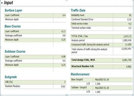
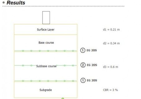
Figure. 4. Unreinforced and reinforced road structure resulting from calculation with AASHTO method
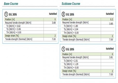
Geogrid design calculations, carried out according to the method and equations shown in the present example, are reported in Table 5 while the results in Table 6: designing at 2 % strain for all geogrids, the base needed to be reinforced with a 20 – 20 kN/m biaxial geogrid (hence it confirms the AASHTO method results); while the sub-base need to be reinforced with one 20 – 20 kN/m geogrid plus one 20– 20kN/m geogrid (while the AASHTO method required just one 20 – 20 kN/m geogrid).
Note that for the geogrid in the base course the prevailing tensile force are the Tp force due to the dynamic load produced by wheels, while the tensile force Tz produced by soil self-weight corresponds to3.1 % of the ultimate tensile strength of the geogrid; at this tensile strength level the long term creep deformation of the geogrid can be assumed negligible.
For the bottom geogrid in the subbase the prevailing tensile force is the Tz force produced by soil selfweight,which corresponds to 12.5 % of the ultimate tensile strength of the geogrid; at this tensile levelthe long term creep deformation of the geogrid, assuming 30 years design life for the road, will be less than εlt =2 %. Adding this long term deformation to the short term deformation (εr = 2 %) will result in atotal deformation equal to 4 % over the whole design life. But the post construction deformation is stillequal to εlt = 2 %. Such post construction deformation in the lowest geogrid, placed at sub-grade interface,can be considered fully acceptable.
Table. 5. Input data for the geogrid design method for Example 2
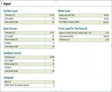
Table. 6. Geogrid design for Example 2
The article was written by;

Business Unit Manager: Geosynthetics & Johannesburg
Maccaferri Africa (Johannesburg Office)
Edoardo Zannoni (Pr Eng); Business Unit Manager: Geosynthetics & Johannesburg
Maccaferri Africa (Johannesburg Office);
Direct: +27 (0) 87 742 2745
Cell: +27 (0) 83 704 1150
Office: +27 (0) 87 742 2710
Fax: +27 (0) 87 742 2749
E-mail: [email protected]
skype id: edoardo.zannoni
Website: www.maccaferriafrica.com