
1. INTRODUCTION
Under repeated loading from traffic the track progressively moves, causing deviations from the desired vertical and horizontal alignment. Ballast tamping is the process to restore the geometry and re-arrange the ballast under the sleeper to keep the track in position and provide it with a homogenous ballast bed. The track geometry should be measured regularly or at least, the track should be tamped at regular intervals to ensure that trains are able to travel safely at the normal speed of the line.
When using inferior machines or other manual tamping methods, geometry is corrected using track jacks and the visual judgement of the Track Master. These methods are not able to provide the quality or durability required for a modern railway line. On any modern railway today, tamping machines with automated lifting, lining and synchronised tamping on open track, turnouts, checked rail sections, splice joints etc. is essential for maintaining the track at the required standards.
Selecting the right machine for the particular track with regards to traffic, length, axle loading, number of turnouts, checked rail sections, spice joints, restricted track etc, has become quite a science. To do so one needs to have a good understanding of the machine types available, their components and functions in order to select the most cost effective solution.
2. BASIC TAMPING PROCESS
The most important working components of a tamping machine are shown in Figure 1.
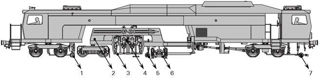
1 – Rear Measuring Trolley 5 – Centre Measuring Trolley
2 – Satellite (Continuous Action) 6 – Lifting and Lining Unit
3 – Tamping Unit Frame 7 – Front Measuring Trolley
4 – Tamping Unit/s
Figure 1: Working Components of Tamping Machine
(09-3X Continuous Action Tamping Machine Illustrated)
Figure 2 provides a schematic illustration of the tamping process in 4 simplified steps.
Step 1 – A basic tamping machine indexes forward and comes to a standstill with the tamping tines of the tamping unit straddling the sleeper to be tamped on both sides.
Step 2 – The lifting and aligning unit works in conjunction with the measuring system and grips the rail under the crown, lifts the track to a predetermined height while correcting any vertical alignment defects in the track and at the same time slews the track to correct the horizontal alignment (simultaneous levelling and aligning).
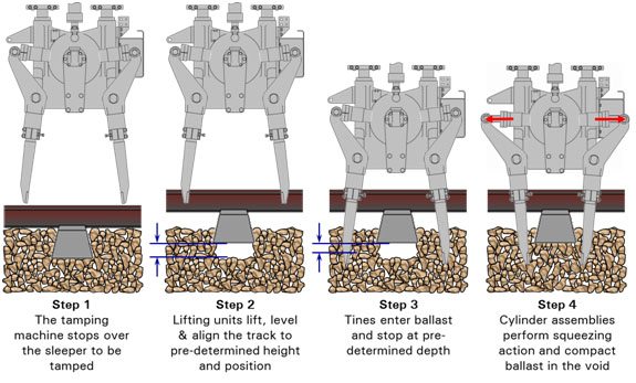
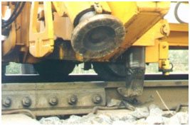
Step 3 – The tamping units are lowered. The vibrating tines enter the ballast and stop at a pre-determined depth. The tines are vibrating in order to fluidise the ballast stone to permit it to re-arrange and settle in a dense matrix. Controlled vibration greatly reduces the force required to penetrate the tamping tines into the ballast without damaging or crushing the ballast stone.
Step 4 – The cylinder assembly exerts a force on the tine arms which perform a squeezing motion of the tines. The tines compact ballast underneath the sleeper in the void created by the lifting process. The tamping machine indexes forward to the next sleeper and the process repeats itself. Behind the tamping machine the track is left at the required geometric standard on a homogeneous ballast bed with restored elasticity.
3. A SPECIALISED TAMPING MACHINE FOR EVERY APPLICATION
3.1. Plain Track Tamping Machines
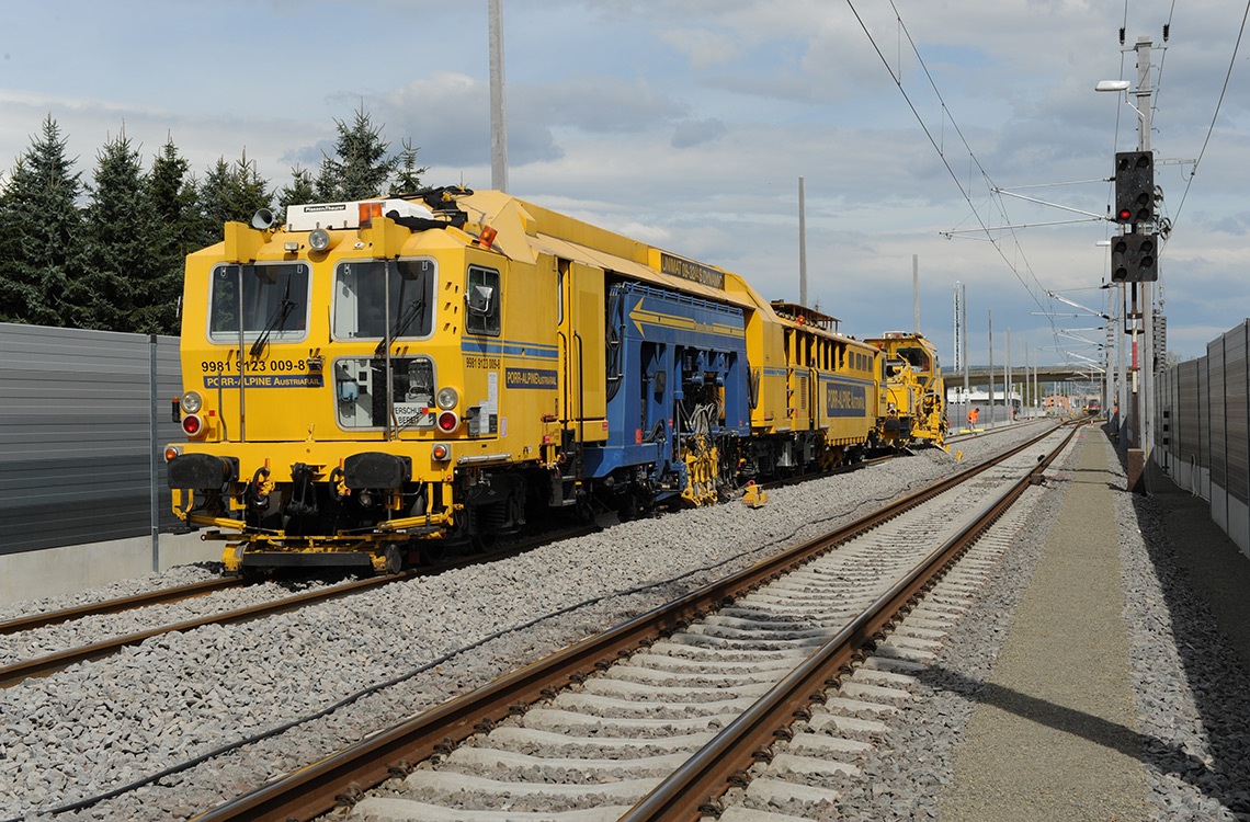
Plain track tamping machines are designed for high production tamping on tangent track on busy lines where the maximum number of sleepers must be tamped in short available maintenance windows. They use technologies such as continuous action tamping and tamping up to 4 sleepers per insertion.
There are, however, many different plain track tamping machine models and not all of them are focused on maximum production, since conditions vary from railway to railway and even between track sections within the same railway.
3.2. Universal Tamping Machines
In turnouts, crossings, splice joints, checked rail sections and other restricted track, some tines may be obstructed by the turnout rails, switch blade, etc. Turnout tamping machines must therefore have specialised tamping units capable of working in these restricted areas, lifting units capable of lifting the track with restricted space, third-rail lifting devices to lift the long sleepers, tamping unit frames that can slew sideways to centre the tamping unit over diverging rails, etc.
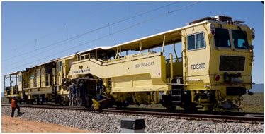
Universal tamping machines, such as the DYNA-CAT shown in Figure 3 are equally capable of tamping plain track at tamping rates similar to plain track tamping machines of the same size.
4. TAMPING MACHINE COMPONENTS
In the previous paragraphs reference was made to the following tamping machine components and features:
4.1. Lifting and Aligning Unit
Tamping machines are equipped with a combined lifting and aligning unit (i) mounted in front of the tamping units (ii) between the bogies (see Figure 4). There are various designs depending on the machine type but they can generally be divided between lifting and aligning units for universal tamping machines and those for plain track tamping machines.
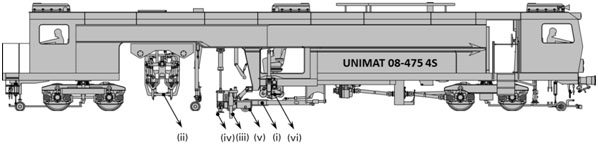
(Unimat 08-475 4S Universal Tamping Machine Illustrated)
4.1.1. Universal Tamping Machines
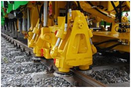
Lifting and aligning units on universal tamping machines (Figure 5) such as the Unimat have special features such as:
· lifting hooks (iii) which grips the rail under the crown or base for lifting in restricted track such as turnouts, checked rails, splice joints, etc;
· roller clamps (iv) for high speed lifting during plain track tamping; and
· either one or two flanged rollers (v) which runs on the rail crown to transfer the lateral force to the track for horizontal alignment.
4.1.2. Plain Track Tamping Machines
Plain track tamping machines are equipped with a lifting and aligning unit with double roller clamps to grip the rail under the crown for high speed lifting and two flanged rollers which run on the rail crown to transfer the lateral force to the track for alignment. See Figure 6.
The positioning of two roller clamps per rail means that the application even on fish-plated joints is automatically secured. The lifting and aligning operation is controlled automatically by the measuring systems. As soon as the target values are reached, lifting and aligning operations are automatically cut out while the track is held in the correct position.
4.2. Measuring System
A fully automatic measuring system (Figure 7) determines the relative difference in the vertical and horizontal positions of the track at a centre measuring trolley which is the recording point (vii) between two reference points, the front (viii) and rear (ix) measuring trolleys. Using this system is called the compensation method.
The relative vertical alignment is established with the use of a steel cord above each rail (x in Figure 7), extended from the rear to the front measuring trolleys. The reference line for relative horizontal alignment is a steel cord (xi in Figure 7), extended along the center of the track.
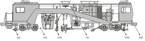
(08-16 SH Universal Tamping Machine Illustrated)
The lifting and aligning unit works together with the measuring system to lift the track to a uniform height removing any vertical defects in the process and to simultaneously slew the track to correct any horizontal defects in the track.
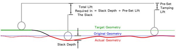
To ensure a residual lift after tamping, research has shown that the minimum lift should be around 20 mm to provide enough space under the sleepers to rearrange the ballast stones. This will however depend on the ballast size; the larger the ballast envelope, the higher the minimum lift will be. Where a vertical alignment defect is encountered, the measuring system will detect the relative vertical difference in height and lift the track by the pre-set height as well as the depth of the vertical alignment defect (also referred to as a slack). Refer to Figure 8.
However, defects which are shorter than the chord length between the front and rear measuring trolleys of the tamping machine can be corrected successfully but if the defects are longer than the chord length, the machine will follow these defects without removing it.
Tamping machines of high quality therefore use optical (Figure 9) or laser equipment mounted to a mobile trolley which is moved 100 to 150 metres ahead of the tamping machine, depending on geography and other conditions. The tamping machine is guided by a straight line which is aimed at a target board on the front measuring trolley [see Figure 7 (xii)]. When the machine moves forward the lifting and ligning wires are adjusted via remote control (or automatically with laser systems) so that the reticule of the viewfinder is lined up with the marks on the target board.
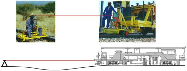
to Permit Removal of Long Wave Defects
This effectively lengthens the chord length to the distance between the rear measuring trolley of the machine and the position of the mobile trolley. This provides utmost accuracy in the vertical and horizontal alignment of tangent (straight) track and is referred to as the precision method.
The measuring system can be supplemented with a computer-based system (for example the WIN-ALC system) which can be used to measure the track and for automatic calculations and/or setting of the offsets in curves. Especially in curves the ALC avoids the time consuming and potentially inaccurate measuring of the curve by hand. It also avoids the resulting alignment errors associated with hand measuring of curves and manual adjustment of the correction values on the machine.
4.3. Third-Rail Lifting Device
Modern universal tamping machines are fitted with a hydraulically operated, telescopic third-rail lifting system on either side of the machine [Figure 4 (vi) and Figure 10], which is synchronised with the combined lifting and aligning unit. This clamp assembly provides controlled lift of the outside turnout rail (the curved closure rail) in the area of the long sleepers during turnout tamping operations and eliminates the need for cumbersome, manually-placed track jacks, hydraulic hose reels and the related labour and maintenance costs.
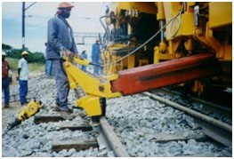
Figure 10 : Third Rail Lifting Device
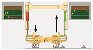
The standard two point lift on the long sleepers of a turnout leads to overstressing and damage to the rail fastenings due to the weight of the long sleeper, the added weight of the turnout rails, as well as the turning moment caused by the long sleeper being lifted at one end. The entire load is carried by the fastenings of the two rails (see Figure 11).
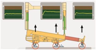
An additional synchronised lift on the outside rail of the turnout distributes the weight of the sleeper and rails across three lifting points and eliminates the turning moment which reduces the lifting force at the middle rail by almost half (see Figure 14). Third-rail lifting devices are therefore essential to tamp turnouts effectively.
4.4. Tamping Units
Due to the variety of requirements for tamping, such as production capabilities, specialised units for tamping turnouts etc, a large variety of tamping unit designs are available to fulfil these specialised requirements. The following are features that set the different tamping units apart:
4.4.1. Number of Sleepers Tamped per Cycle
The number of sleepers that are tamped per cycle (insertion) determines the production capability of the machine. Single sleeper tamping machines are still very common since high production is not always required and a lower production at a lower machine price can be preferred.
High production machines are extremely cost effective when their capacity is optimised, especially on high density lines. The fewer number of occupations required to maintain the tamping cycle required for the traffic throughput, may bring about higher income to the railway when the opportunity cost of traffic is considered. In other words, if fewer occupations are required to tamp the track, more trains can be running resulting in more income for the railway.
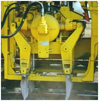
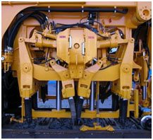
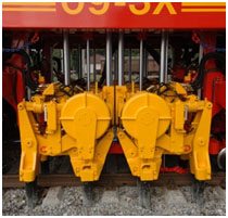
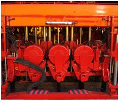
Figure 13: Examples of Tamping Unit Layouts
If necessary, multiple sleeper units can be switched to single sleeper tamping where sleepers out of square or poor sleeper spacing or restricted track is encountered.
4.4.2. Specialised Turnout Tamping Units
In turnouts where track is restricted, some of the tines may hit an obstruction such as the switch blade or curved closure rail of the turnout portion. This problem is addressed with the use of split tamping units.
Split tamping units are in principle longitudinally divided in two (field side and gauge side), and can be raised and lowered individually for unparalleled versatility (vertical split). See Figure 15.
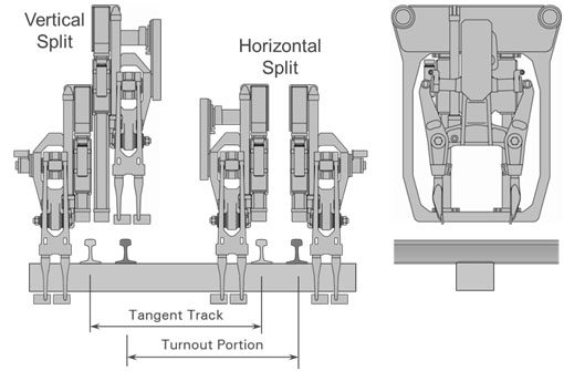
Each one of the total of four units can be lowered and put into action separately from the other. Furthermore, some split units can individually be displaced laterally as well (horizon split) to find the best area in the restricted track to enter the ballast. The split units can be locked together, in which case they will act like conventional plain track tamping units.
The units can also be displaced laterally on horizontal guide columns so that the tamping tools are centred exactly over the area to be tamped.
4.5. Auxiliary Satellite Frame for Continuous Action Tamping
A conventional tamping machine must move from sleeper to sleeper for the tamping operation. The machine must therefore accelerate and brake again between sleepers and is referred to as index tamping. Though this principle is still used on many modern tamping machines, its production capability is limited by acceleration and braking limitations. The limit for index tamping using a 2-sleeper tamping machine is around 33 sleepers per minute. Therefore, only lower production, lower cost and specialised tamping machines use index tamping.
To increase tamping production rates, continuous action tamping was developed whereby the tamping units are mounted to an auxiliary satellite frame which runs on its own axle/s separate from the main frame. This principle is common on high production tamping machine used on most high capacity lines around the world. Continuous action tamping allows continuous motion of the main frame while the cyclic braking and acceleration for the tamping action is performed by the auxiliary frame. Only around 20% of the machine mass must therefore be braked and accelerated.
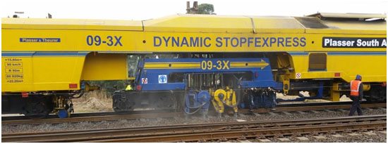
Continuous Action Tamping Machines
When this principle is combined with multiple sleepers tamped per insertion, very high tamping rates are possible. The 09-3X tamps 3 sleepers per insertion and achieves very good results in South Africa.
The continuous action principle is available on universal tamping machines as well providing utmost production on both turnouts and plain track. These machines combine continuous action tamping with up to two-sleeper split tamping units and integrated dynamic stabilisation combined in one machine. The DYNA-CAT (Figure 3) is a good example of one such machine and is a very productive machine in South Africa.
4.6. Wheelbase
Wheelbase refers to the distance between the centre of the bogies or centre of two single axles of the tamping machine. During the tamping process, the track is lifted at the lifting unit by at least 20 mm to ensure a residual lift. Where a vertical alignment defect is encountered, the lift becomes progressively more by the depth of the defect as was illustrated in Figure 8.
The importance of wheelbase is illustrated in Figure 17, which shows the maximum rail stress (EN-Standard Limit) vs the lift applied by the machine at the lifting unit on tangent track with UIC60 rails and concrete sleepers.
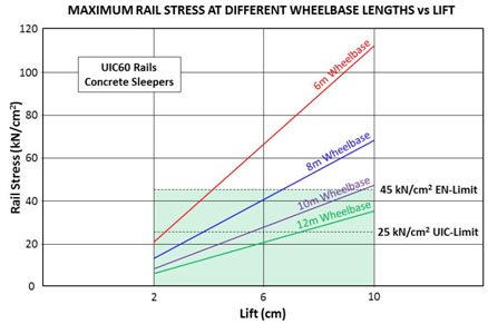
Tamping machines with different wheelbases were then used to lift the rail, the rail stress established and the results plotted.
The graph clearly shows that tamping machines with a 6 metre wheelbase cannot lift more than approximately 40 mm before the maximum rail stress is exceeded due to the bending radius of the rail. Considering that the minimum maintenance lift by a tamping machine is already around 20 mm, a 6 metre wheelbase machine will not be able to even lift out a vertical alignment defect exceeding 20 mm in one pass. This machine will therefore not be appropriate for heavy haul lines where a larger ballast stone is used. This research also highlights the danger of over stressing the rail during tamping when short wheelbase machines are used.
For this and other reasons such as weight, smaller machines are not able to lift turnouts sufficiently, especially those on concrete sleepers. They should therefore not even be considered because not only will they damage this expensive track component but they would also be unable to correct the geometry.
5. DYNAMIC STABILISATION
The discussion on tamping is not complete without mentioning the importance of dynamic track stabilisation behind tamping, especially on high capacity lines. It is even more important behind tamping after ballast cleaning on newly constructed lines to avoid speed restrictions that are normally imposed to allow the track to settle and increase its resistance to lateral displacement before the line can be opened at normal track speed. This settlement is normally irregular and requires re-tamping soon after.
The dynamic stabilising machine sets the track in horizontal oscillation while applying a controlled static vertical load (Figure 17). In this way the track is actually “rubbed” into the ballast which settles in a dense homogenous matrix of which the resistance to lateral displacement is up to 70% of what it was before ballast cleaning.
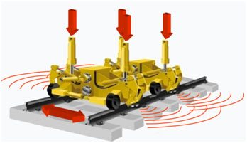
Figure 17: Stabilising Units Located Between the Bogies
Independent studies have shown that the stabilising machine increases the durability of the geometry after tamping by up 30%, thereby reducing interruptions to income generating traffic and damage to track material.
Today dynamic track stabilising is an integral part of tamping and ballast cleaning on nearly all high capacity railway lines around the world.

Complete description about Track Temping Machine, thank you.
Please what is the acceptable tolerance for lift and shift.
How much is maximum lifting height?
How to do adjustment on various curve?
Do we need to control for lifting and aligning to be within allowable track geometry (eg. Gradient 0.76% or something like that)