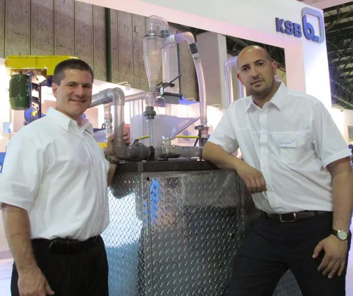
KSB Pumps and Valves recently gave technical staff of local mines the opportunity to view the inside working and dynamics of a slurry pumping system with the aid of a fully transparent operational slurry loop model.
The working model depicts a typical mill cyclone feed application and is used as a training aid to visualize flow of materials and the effects of inclines, declines and different flow rates on sediments. It has a clear casing pump, cyclone and pipes for visualization of flow patterns. It also uses different sized and colored glass beads to represent solids.
Speaking at this year’s Electra Mining exhibition in Johannesburg recently, Mohamed Trabelsi, KSB product manager for slurry pumps, said that the slurry loop model was built to give engineers an opportunity to study various parameters (such as pipe diameters, inclines, flow rates etc) and their effect on a slurry pump system.
Research and development
“KSB worldwide has done a tremendous amount of research and development on slurry pumping and we wanted to show our customers how the systems work and the do’s and don’ts of designing a slurry system. It also showcases the expertise of KSB in terms of design, research and development, as well as our system integration expertise on any level.
“The model begins with a clear casing pump, driven by a variable speed drive (VSD) which allows speed to vary from 150 – 2000rpm. The system then splits into two sections with different pipe diameters in order to see the effect of different velocities on slurry transport.
The slurry is then transported into two sections where it goes into a 45° degree section followed by a vertical loop. This shows what happens to slurry in different inclines. To do this it uses different size particles of the same specific gravity (2.6 which is a common SG in minerals) with different colours to indicate the effect on settling velocities.
“The flow then goes into the cyclone where one can see both the underflow and the overflow. For purposes of the demonstration both under and overflow go back into the sump, but in a typical processing application the fine material would proceed to the next processing step, while the underflow (Larger solids) would go back to the mill for further grinding,” explained Mohamed.
Pipe dynamics
Richard Inglett of KSB Pumps and Valves in the USA continued that the model was purpose built to give users a visual representation of slurry pumping. It was also designed to answer technical dilemmas that face designers and engineers on a daily basis. “Some of the different mines operational staff took the opportunity to see what happens inside a pipe and visually see how bends and velocities effect flows.
“For example, when viewing the two pipes (2 inch and 1 1/2 inch diameter) at full speed you can see settling slurries on the 2 inch pipe due to the larger diameter and reduced flow. On different inclines it also shows that on the 45 degree pipe you can see unsteady bed developments which represent the worst case for the transport of settling slurries.
For long distance pipelines, it shows that the degree of incline must be taken into account for the system calculations. Even in short systems, inclined sections can cause instability and plugging. It also shows that, when possible, you would rather have horizontal or vertical sections than gradual inclines/declines
Pump damage
“The reason for the VSD is to show what happens to materials at different pump speeds and where it reaches its best efficiency point. At this point there is minimal recirculation of fluids in side the pump. Away from BEP, the system shows how recirculating slurry within the pump (that is not discharged) becomes entrapped. These slurries are then driven between the impeller and the suction liner and can lead to premature pump wear and a shortened operational lifespan,” says Richard.
Mohamed concludes that the system highlights the importance of proper pump selection and shows users how slurries behave throughout the pumping system.

Leave a Reply