Utility strikes usually occur in conditions of partial information, not complete ignorance. Crews may have records, paint marks, locator responses, or prior survey data and still misunderstand what those sources actually establish. Utility locating equipment can reduce that uncertainty, but no single technology answers every question about a buried facility.
The useful question is therefore not which locating technology is “best.” It is which uncertainty still controls the risk before excavation or drilling begins, and which method can reduce that uncertainty. A known metallic line, an undocumented PVC service, and a congested HDD crossing require different evidence.
| Key findings
• No surface method establishes every dimension of utility certainty. Existence, identity, horizontal alignment, depth, size, configuration, and completeness are separate questions. • Active electromagnetic locating is strongest when the operator can control which conductor carries the signal. Direct connection generally provides more target selectivity than clamp application, and both provide more selectivity than broad induction. • GPR can add evidence for nonconductive or undocumented targets, but soil, pavement, depth, target size, and subsurface clutter can limit detection. • Physical exposure provides the strongest confirmation of actual utility position at a specific conflict point. It does not prove the utility follows the same line or elevation between exposures. |
1. Utility location is a multi-dimensional problem
Field teams often describe a utility as either “located” or “not located.” That binary description hides several independent questions. A complete investigation may need to establish:
- whether a facility exists;
- which facility produced the detected signal;
- where it runs horizontally;
- its vertical position;
- its size, material, and configuration;
- whether all relevant utilities in the work area have been found.
A method can answer one question well while leaving another unresolved. An electromagnetic locator may trace a conductive gas line over a long distance without revealing an untraceable plastic service nearby. GPR may show a subsurface anomaly without identifying its owner or service. A pothole can establish one pipe’s actual position at a conflict point without proving its elevation 30 ft away.
The central principle is simple: location confidence has several dimensions, and each method reduces only some of them.
2. Evidence hierarchy: records, markings, geophysics, and exposure
The ASCE utility engineering quality-level framework, also used in FHWA Subsurface Utility Engineering guidance, helps distinguish the type of evidence behind a utility position. The levels do not rank one instrument against another; they describe how the position was established.
| Quality level | Primary information source | What it mainly establishes |
| QL-D | Existing records and recollections | General existence and expected route |
| QL-C | Surveyed visible utility features | Relationship between records and visible infrastructure |
| QL-B | Surface geophysical methods | Horizontal position and probable alignment |
| QL-A | Physical exposure and survey | Precise horizontal and vertical position at the exposure point |
QL-B and QL-A answer different questions
QL-B information still depends on surface geophysical inference. A well-executed QL-B investigation can map a utility corridor efficiently, but it does not convert an inferred position into a directly observed one. QL-A physically exposes and surveys the facility at a specific point.
That distinction becomes critical when allowable clearance is small. A useful surface trace can support route planning; an exposed point can establish the actual local position.
811 markings are essential, but they are not a three-dimensional survey
The 811 process supports damage prevention by notifying utility owners and producing markings or responses before excavation. Those markings remain one part of the evidence set rather than proof of exact underground geometry.
A surface mark may not establish exact depth, diameter, sidewall position, elevation changes, underground bends, abandoned facilities, private facilities, or the separation between closely spaced parallel utilities. On a straightforward excavation, marks and conventional locating may provide enough information for the planned work. A congested HDD crossing with limited clearance may require stronger confirmation.
3. Electromagnetic locating: target identity depends on signal control
Electromagnetic (EM) locating traces conductive underground utilities by detecting the field around a conductor. The operator’s confidence in target identity depends heavily on how the locating signal reaches that conductor.
Three active application methods are common: direct connection, clamp application, and induction. They can all produce usable traces, but they do not provide the same control over which conductor carries the signal.
Direct connection
Direct connection applies the transmitter signal to the intended conductor or tracer wire. When the target is conductive, an appropriate connection point is accessible, continuity is intact, and the circuit provides a usable return path, the operator has strong control over where the signal entered the system.
That control reduces target-identity uncertainty, especially in congested corridors. It does not eliminate coupling to adjacent conductors, broken tracer wires, distorted fields, or the basic limitation that plastic pipe without a usable tracer wire may provide no conductive path.
Clamp application
A transmitter clamp applies the signal around an accessible cable or conductor without a direct electrical connection. It preserves more target control than broad induction because the operator selects a specific conductor, although signal transfer may be weaker than a good direct connection and the target still must be conductive and physically accessible.
As a general target-selectivity hierarchy, direct connection provides the most control, followed by clamp application and then induction. This is a hierarchy of target identity, not a claim that one method always produces the best overall locate.
Induction
Induction places a transmitter field into the ground from the surface, so nearby conductors can pick up the signal. It is useful when no connection point is available or when the crew needs a rapid search for conductive facilities.
The same mechanism creates ambiguity. Several conductors can receive the signal, and the receiver may follow a nearby line instead of the intended target. A clean route and strong response therefore do not, by themselves, prove correct identity.
Inductive results become more credible when they agree with independent evidence: known access points, route continuity, records, visible appurtenances, another signal application method or frequency, another locating technology, or physical exposure at a critical point.
Passive modes
Passive EM modes detect energy already present on buried conductors rather than a signal applied by the operator. They work well as a supplementary sweep for some energized or unexpectedly conductive targets, but they provide weaker target identity and cannot prove completeness.
A passive sweep can miss non-energized lines, nonconductive utilities, deep conductors with weak responses, or facilities that carry too little detectable energy. “No signal” and “no utility” are not equivalent conclusions.
Figure 1. Target selectivity depends on how the transmitter signal is applied. Direct connection and clamp application give the operator more control over the intended conductor than broad induction.
4. GPR and broad-area EM address different gaps
Ground penetrating radar (GPR) uses reflected electromagnetic pulses rather than current carried by a conductor. That physical difference matters because GPR can provide evidence for some targets that conventional EM tracing cannot energize, including PVC or polyethylene pipe, utilities without usable tracer wires, abandoned facilities, undocumented utilities, and other buried objects.
Its main contribution is often completeness rather than identity. If a crew successfully traces every conductive facility shown in the records, that result still does not prove that the work area contains no nonconductive or undocumented utility. GPR can test that remaining uncertainty with an independent physical principle.
GPR has site-dependent limits
Radar performance changes with soil and site conditions. Clay-rich or electrically conductive ground, saline conditions, reinforced pavement, small or deep targets, weak contrast with surrounding material, rebar, and other buried structures can reduce penetration or complicate interpretation.
A missing radar response can therefore mean either that the target is absent or that conditions prevented useful detection. Those explanations must remain separate.
Combining EM and GPR adds value when the methods fail differently
Consider a corridor with a steel gas main, conductive telecommunications cable, PVC water service, abandoned metallic pipe, and an undocumented private facility. Direct-connect EM may trace the gas and communications lines well but miss the PVC service. GPR may show a target where EM shows nothing. An abandoned metallic pipe may appear in both datasets, while records help explain some features but not others.
The value comes from independent agreement. Repeating the same measurement under the same assumptions can confirm repeatability; combining methods with different failure modes can test a broader set of uncertainties.
Broad-area electromagnetic methods
Time-domain electromagnetic induction and related broad-area methods can extend metallic-target detection where crews cannot directly connect to every line. They can help identify cast iron, ductile iron, unknown metallic targets, or conductive facilities without accessible connection points.
They also respond to unwanted metal. Vehicles, fences, reinforced concrete, dumpsters, nearby structures, overhead electrical infrastructure, and closely spaced utilities can complicate interpretation. These systems expand coverage, but they do not remove the need to identify the target or confirm a critical conflict physically.
5. Depth estimates are useful; physical exposure changes the evidence level
Modern utility locators can estimate depth and help crews build a working model of subsurface geometry. Those readings remain indirect. Distorted fields, adjacent conductors, target geometry, signal frequency, transmitter placement, receiver position, ground conditions, and operator technique can all affect the displayed value.
A depth estimate can look internally consistent and still be wrong if the receiver follows a distorted field or the wrong conductor. Locator depth is therefore most useful as an investigative input, not as a substitute for direct measurement when exact clearance controls the job.
Physical exposure
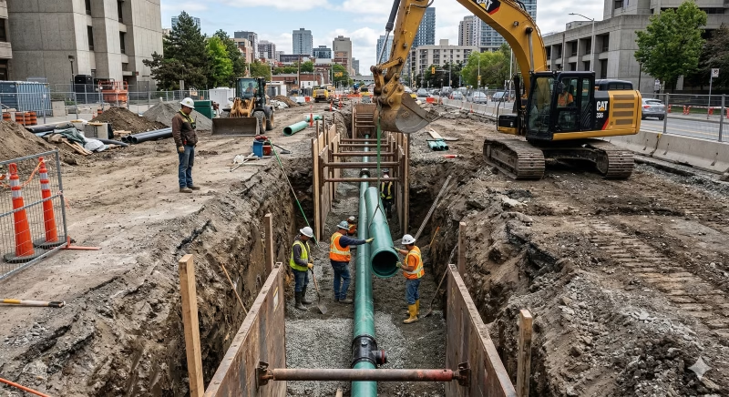
Potholing or daylighting lets the crew observe the facility directly and measure its position. At the exposed point, the team can confirm horizontal position, vertical elevation, diameter, material, configuration, and the relationship to the proposed work. This is why physical exposure corresponds to QL-A information.
The limitation is spatial. One test hole confirms one point. Utilities can bend, rise, drop, branch, change material, cross other facilities, or enter a structure between exposures. Physical exposure provides the strongest local positional evidence, not continuous certainty along an entire alignment.
6. HDD creates two independent location problems
Horizontal directional drilling adds a second trajectory that the crew usually cannot see directly. The project must answer two separate questions: where is the existing utility, and where is the drill head or bore path?
A utility locating system addresses the first question. An HDD locating or guidance system addresses the second. Accurate bore tracking cannot compensate for an incorrect model of the existing utility.
For example, suppose the crew models a utility at 5 ft deep, while the actual facility is 6 ft deep. If the HDD operator accurately tracks the drill head at 6.5 ft, the guidance system can perform correctly while actual clearance becomes much smaller than planned. The tracking system did not fail; the utility model was wrong.
Critical HDD crossings therefore depend on confidence in both trajectories. Improving only one leaves the other source of uncertainty unchanged.
Figure 2. HDD clearance depends on two independent positions: the existing utility and the drill head or bore path. Reliable guidance cannot compensate for incorrect utility information.
7. A risk-based workflow reduces uncertainty step by step
A strong investigation starts with the evidence already available and then targets the questions that remain unresolved. The sequence below uses each method for a different purpose rather than treating every project as an instrument-selection problem.
- Review records. Collect available GIS data, utility-owner maps, as-builts, previous surveys, SUE data, and project utility information. Records establish context and expected routes; they do not prove current underground position.
- Compare records with visible infrastructure. Check manholes, valves, hydrants, meters, pedestals, poles, and service entrances. A conflict between records and visible features should increase uncertainty and trigger investigation rather than an assumption that one source is correct.
- Complete the applicable 811 process. Review utility responses and surface markings before work starts. Unexplained gaps, conflicting marks, or inconsistent information should trigger additional investigation.
Figure 3. Risk-based utility investigation workflow. Each step should reduce a specific uncertainty before the project moves to a higher-consequence action.
- Trace known conductive utilities. Use active EM where appropriate. Direct connection generally provides the strongest target selectivity, clamp application can preserve selectivity when direct connection is impractical, and induction can cover cases where a physical connection is unavailable.
- Search for what targeted locating may miss. Use passive sweeps and complementary geophysical methods. Add GPR when nonconductive utilities, incomplete records, abandoned lines, or private infrastructure remain plausible and site conditions support useful radar performance.
- Compare the evidence. Look for agreement and disagreement among records, visible features, 811 marks, active EM traces, passive responses, GPR anomalies, and the known layout of the utility system. Agreement increases confidence; disagreement defines the next question to solve.
- Expose critical conflicts. Use potholing or daylighting when remaining positional uncertainty could affect clearance. The higher the consequence of a wrong assumption, the stronger the case for direct verification.
- Survey and document exposed facilities. Record the horizontal position, elevation, utility type, material, diameter, and test-hole location needed for construction control and future reference.
- Control the construction path. A correctly located utility can still be struck if excavation or drilling enters the wrong space. Utility investigation and construction-path control must therefore work together.
8. Which methods reduce the most uncertainty?
No method dominates across every uncertainty. The useful comparison is the type of information each method adds and the limitation that remains afterward.
| Method | Main uncertainty reduced | Main limitation |
| Records / GIS | Expected existence and route | Can be outdated or incomplete |
| Surface feature survey | Correlation with visible infrastructure | Does not define full underground geometry |
| Passive EM | Some unexpected conductive utilities | Weak target identity and completeness |
| Induction EM | Search and tracing without a connection | Can energize multiple nearby conductors |
| Clamp EM | More selective signal application | Requires an accessible conductive target |
| Direct-connect EM | Selective tracing of a known conductive utility | Requires a usable conductive path |
| GPR | Some nonconductive and unknown targets | Performance depends heavily on site conditions |
| Broad-area EM imaging | Unknown metallic targets | Metallic clutter can interfere |
| Multi-method QL-B investigation | Area-wide utility mapping | Still depends on indirect detection |
| QL-A physical exposure | Precise position at one point | Does not establish continuous alignment |
The practical conclusions are scenario-specific:
- For a known conductive utility, direct-connect EM generally reduces target-identity uncertainty more effectively than induction.
- For unknown or nonconductive utilities, GPR can add information that conventional EM tracing cannot provide.
- For a complex corridor, combining methods can reduce more uncertainty because the methods fail for different reasons.
- For a critical conflict where exact clearance matters, physical exposure provides the strongest local positional confirmation.
9. Failure modes that create false confidence
Utility strikes do not always follow an obvious locating failure. Plausible data become dangerous when crews treat them as stronger evidence than they are.
- Following the strongest signal. The strongest electromagnetic response does not always belong to the intended utility. Coupling can place energy on an adjacent conductor.
- Assuming no signal means no utility. A broken tracer wire, nonconductive pipe, weak passive response, excessive depth, or poor detection conditions can all produce no useful signal.
- Treating paint as underground geometry. A surface mark does not show the facility’s complete three-dimensional position.
- Treating GPR as universal detection. Radar performance changes with soil, moisture, depth, pavement, target characteristics, and subsurface clutter.
- Treating displayed depth as surveyed depth. An instrument estimate and a physically exposed elevation represent different evidence levels.
- Potholing one point and assuming a constant route. Utilities can change direction and elevation between exposures.
- Verifying the utility but ignoring the bore. For HDD, actual separation depends on both utility position and drill-head position.
More locating technology helps only when it adds independent evidence
Adding a second instrument does not automatically double confidence. It helps when the second method tests something the first method could not establish. Records can describe the expected network; direct-connect EM can trace a known conductor; GPR can search for nonconductive or unknown targets; physical exposure can confirm the critical crossing.
Repeated agreement from the same physical principle can show consistency. Independent agreement is more valuable when the goal is to reduce different failure modes.
10. Investigation level should follow the consequence of being wrong
Not every project needs the same amount of locating work. A shallow excavation in an uncomplicated corridor does not carry the same uncertainty or consequence as an HDD crossing near a high-consequence utility. As the consequence of a wrong assumption increases, the project should reduce more uncertainty before excavation or drilling begins.
A useful progression is: records → field correlation → targeted locating → complementary geophysics → physical verification. This sequence is not a rule that every project must complete every step. It is a decision framework: stop only when the remaining uncertainty is appropriate for the work ahead.
The strongest method is therefore not the instrument with the longest range or the cleanest signal. It is the method that reduces the uncertainty still capable of causing a strike. Conductive targets often favor selective active EM; unknown or nonconductive targets may require GPR or another complementary method; complex corridors benefit from independent evidence; and critical clearance points may require physical exposure.
No practical locating technology can guarantee detection of every buried utility under every site condition. Effective strike prevention depends on matching the evidence level to the consequence of error and controlling both the utility position and the actual construction path.